
|  |
|  |
|  |
|  |
|  |
|
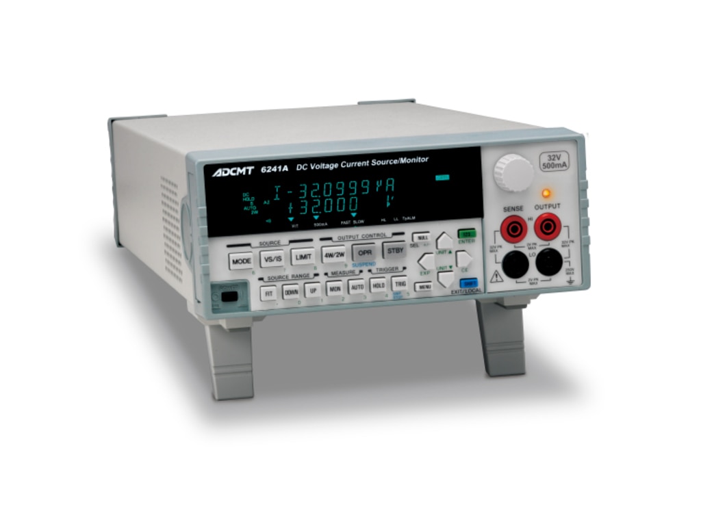
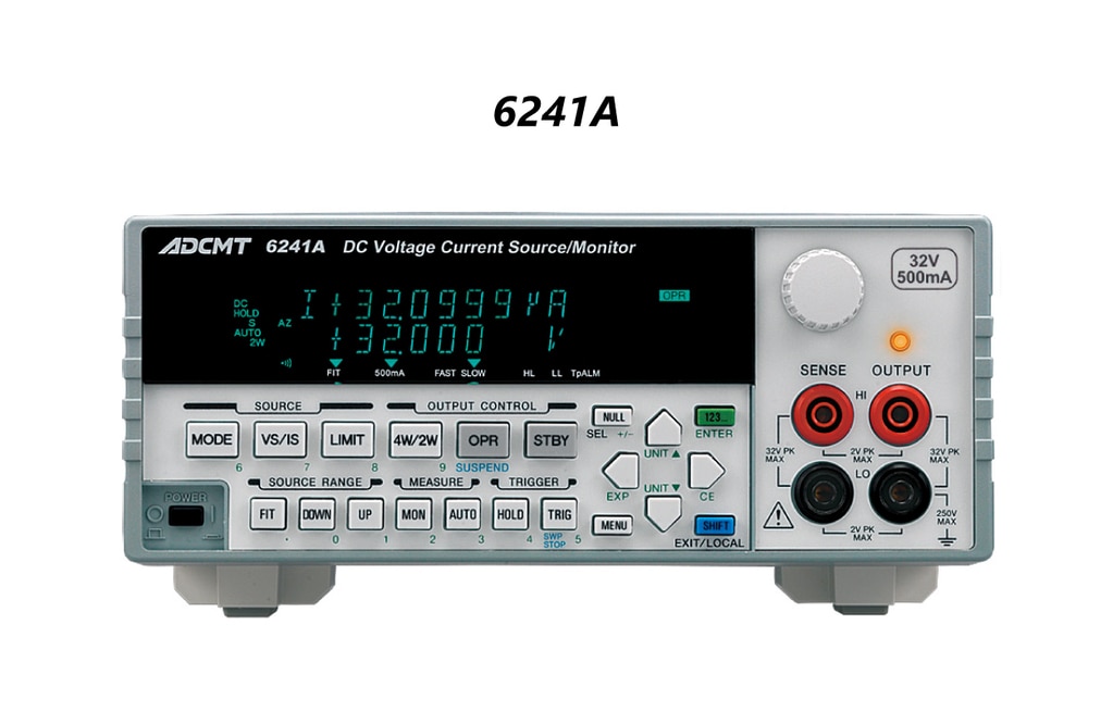
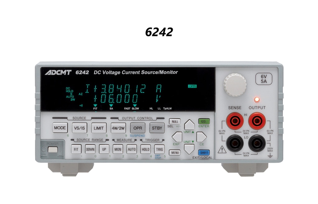
DC Voltage Current Source/Monitor
6241A / 6242
- Wide ranging source/measurement
- 6241A Voltage: 0 to ± 32 V Current: 0 to ± 500 mA
6242 Voltage: 0 to ± 6 V Current: 0 to ± 5 A - High source/measurement resolution
Source : 10 μV/1 nA Measurement : 1 μV/100 pA - Basic source and measurement accuracy: ±0.02 %
- Pulse measurement with a minimum pulse width of 50 μs and 1 μs step
- Two slope linear sweep function
- Sink-enabled bipolar output l GPIB and USB interfaces
The 6241A/6242 is a DC voltage and current source/ monitor capable of 4½-digit generation and 5½-digit measurement with high accuracy of ±0.02 %.
The instrument has two slope linear sweep, linear sweep, fixed sweep and random sweep functions, and is also capable of pulse measurement with a minimum pulse width of 50 μs and low voltage/current measurement with a resolution of 1μ V/100 pA. Thus, it can be used for a wide range of applications for evaluation in R&D of semiconductors and other electronic components, or for characteristic tests in a production line.
The sink-enabled bipolar output, the individual HI/LO limiter function and the suspend function are effective in evaluation of batteries and power ICs.


Features
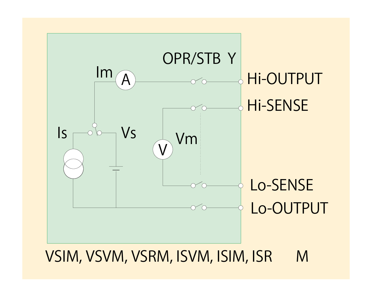
Source and measurement function
Voltage/current source and voltage/current/resistance measurement can be selected by specifying the source and measurement functions.
Output range
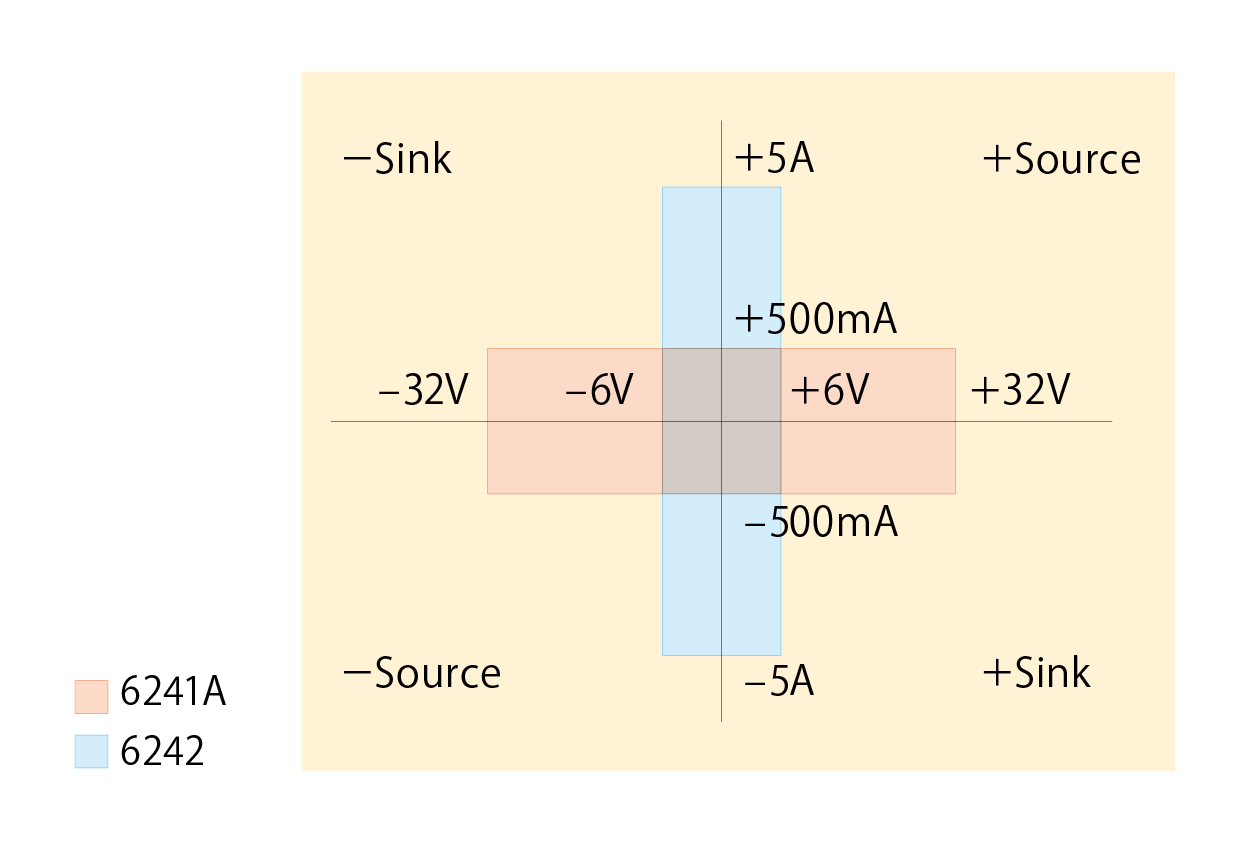
6241A Voltage: 0 to ± 32V
Current: 0 to ± 500mA
6242 Voltage: 0 to ± 6V
Current: 0 to ± 5A
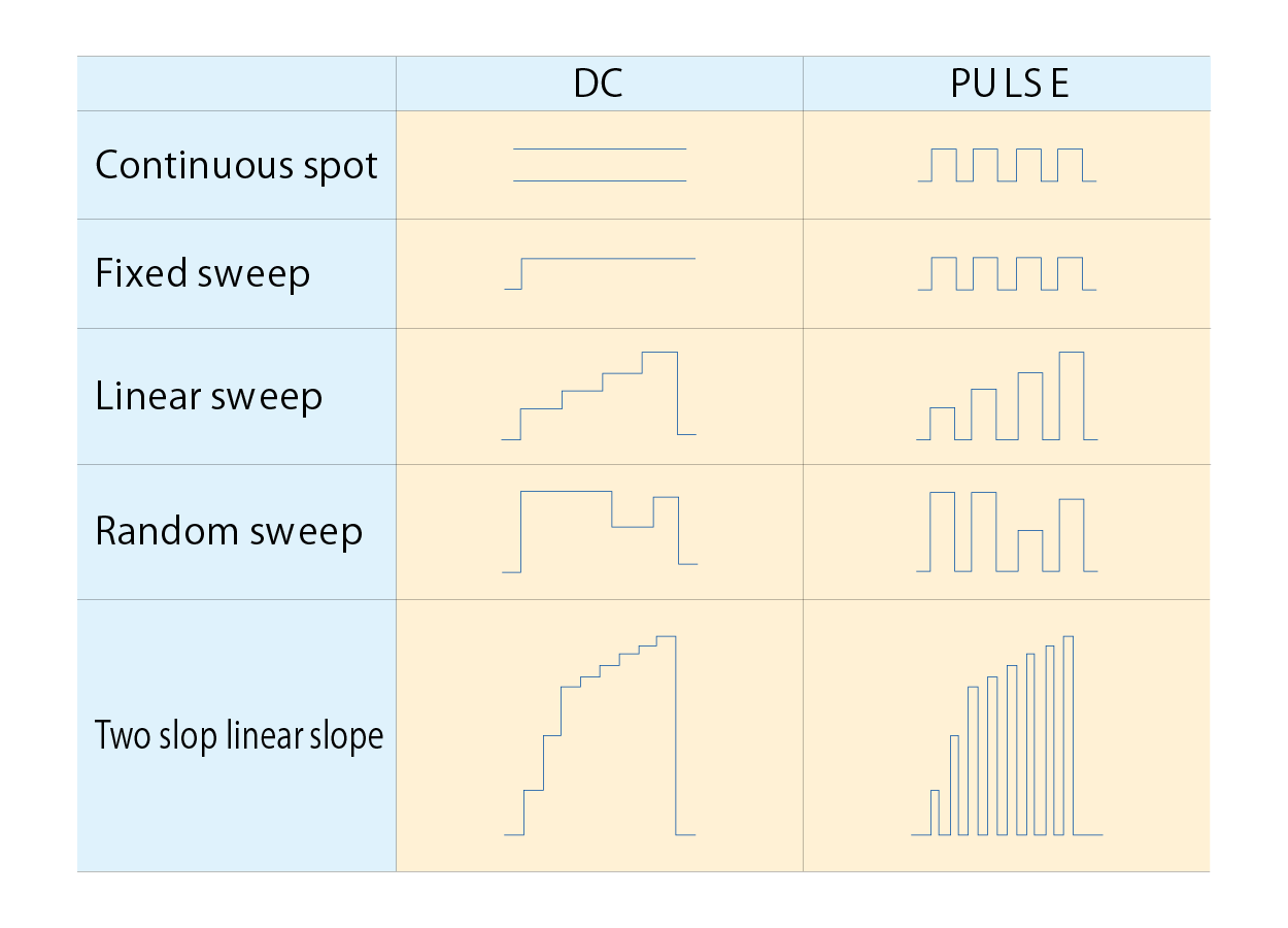
Voltage/current source mode
There are four source modes; DC, pulse, DC sweep, pulse sweep. Then, the sweep modes are classified into four sweep types: fixed sweep, linear sweep, random sweep (user programmable sweep), two slope linear sweep (linear sweep with step value switching). The minimum pulse width is 50 μs. The minimum cycle is 2 ms, or 500 μs without measurement.
Individual settings of HI/LO limiters
In voltage/current source, the HI/LO limiter settings are very important. The 6241A/6242 has a function that can set the HI and LO limiters individually. Furthermore, for the voltage-limiter, both HI and LO limiters can be set homo-polar. This prevents a capacitor or a battery from being over-discharged. Also, it is suitable for evaluating devices such as LDs that are used at a constant current and do not tolerate reverse voltage application.
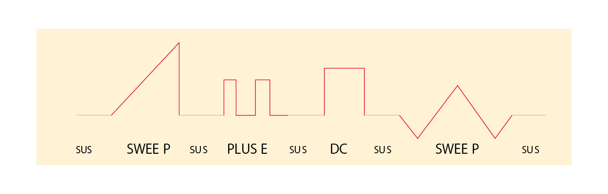
Suspend function
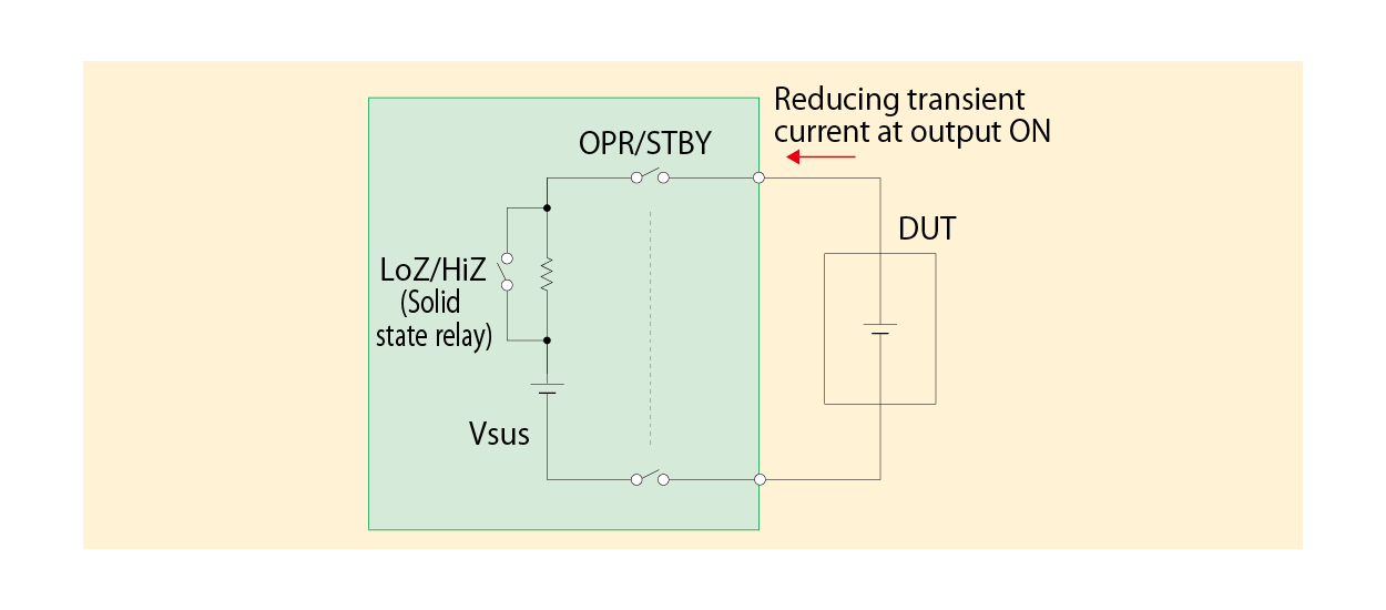
The 6241A/6242 can select from three output OFF statuses; STBY (output relay OFF), HiZ (output relay ON and high resistance), and LoZ (output relay ON and low resistance). Using this function can omit unnecessary relay ON/OFF action, which reduces deterioration of the throughput due to relay operation time and improves the life span of the relay.
In addition, the setting of a suspend voltage (voltage in HiZ and LoZ status) prevents transient current sink that occurs at a connection of a voltage output device such as a battery.
When a conventional generator or electronic load is connected with a battery, the output voltage is 0V, and then the setting current starts flowing. In this case, the moment that it is connected, transient current sink occurs, causing unnecessary battery discharge. On the other hand, by setting a suspend voltage, the 6241A/6242 is connected in high-impedance state at the specified voltage and then the setting current flows. This prevents unnecessary discharge at the connection to a battery.
For the 6241A/6242, the source modes can be switched in such suspend status, which reduces deterioration of the throughput due to source mode switching
| Output OFF status | Output relay | Output status | Current limiter setting value |
|---|---|---|---|
| LoZ | ON | Vsus, low resistance |
VS: Setting current limiter (IL) IS: 30 digits in the setting current range |
| HiZ | ON | Vsus, high resistanc | 300 nA |
| STBY | OFF | Open | ー |
Vsus: Setting suspend voltage (default: 0 V)
High-speed response and low noise
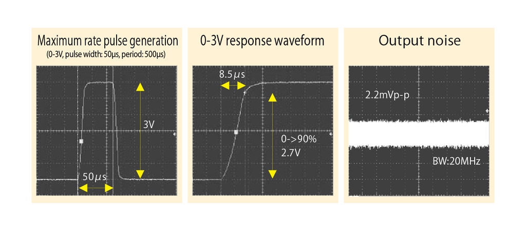
The typical waveform and output noise of the 6241A/6242 are shown below. The response of 0-3 V is approximately 8.5 μs at 0-90 % rising time, and the output noise is approximately 2.2 mVp-p at DC-20 MHz.
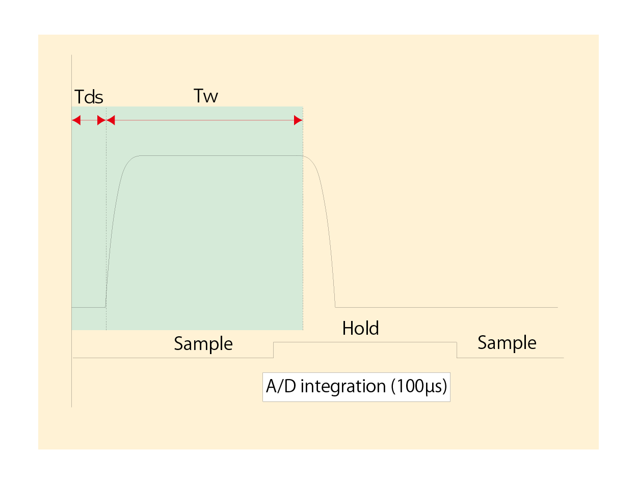
Sample hold measurement
Sample hold measurement is available in the pulse mode and the pulse sweep mode. Measurement holds an input signal immediately before pulse falling edge, and A/D conversion is implemented for integration time of 100 μs. In this case, the setting measurement delay time is ignored.
Applications
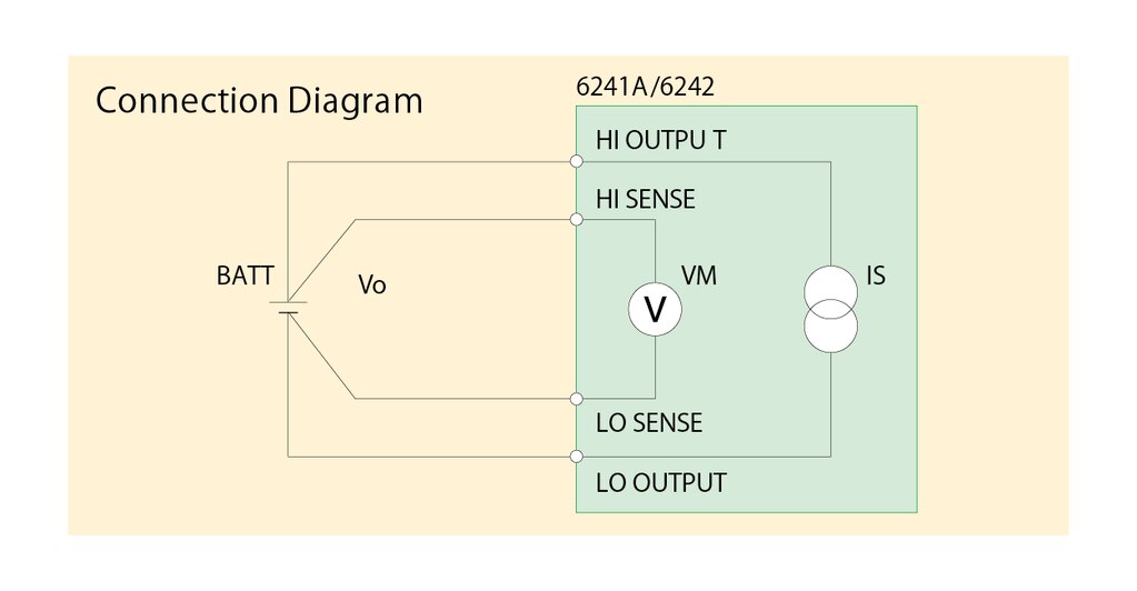
For battery charge/discharge tests and power device evaluation
The 6241A/6242 handles bipolar output and is capable of ± source and ± sink operations. Therefore, it has achieved 0V sink operation which cannot be done by a general electronic load. With its pulse source function, it can be used for evaluation of batteries and power supply devices used for various portable devices.
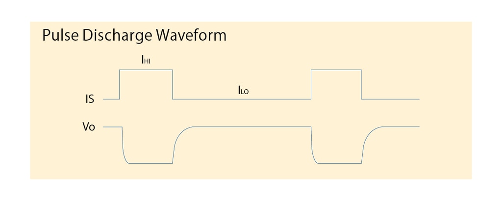
- Capable of handling pulses of cellular phones with a minimum pulse width of 50 μs and 1 μs step.
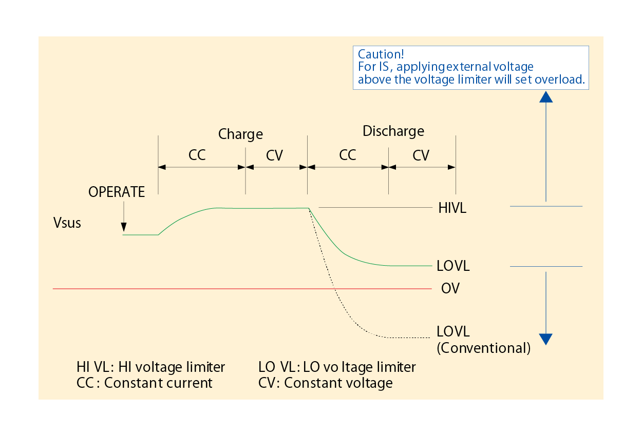
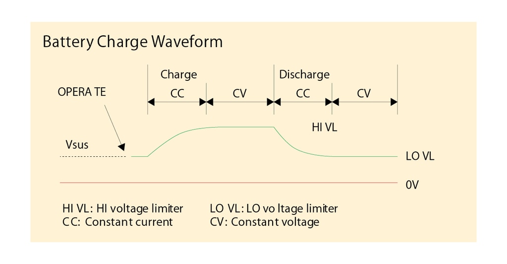
- Capable of CV/CC operation for both charging and discharging by using HI/LO voltage limiters.
Both HI and LO voltage limiters can be set to + value (or – value). If HI is set to +1.8 V and LO to +1.2 V, for instance, the mode becomes constant voltage operation when the battery voltage reaches +1.8 V, and discharging terminates when it reaches +1.2 V. - Avoids unnecessary discharge at output ON by setting a suspend voltage (Vsus). A general power supply is at 0V or in open status of 0V when output is OFF, and a low impedance state of 0V always occurs when output is ON.
At this time, the battery is being discharged unnecessarily for a moment. However, by setting the suspend voltage of the 6241A/6242 to +1.2 V, for instance, unnecessary discharge can be avoided since the voltage of the output terminal is +1.2 V the same as that of the battery, even in a temporary low impedance state that occurs when the output is ON. This function is also useful for preventing FET from being set to ON instantaneously at output ON when it is used as a gate voltage of J-FET or GaAsFET.
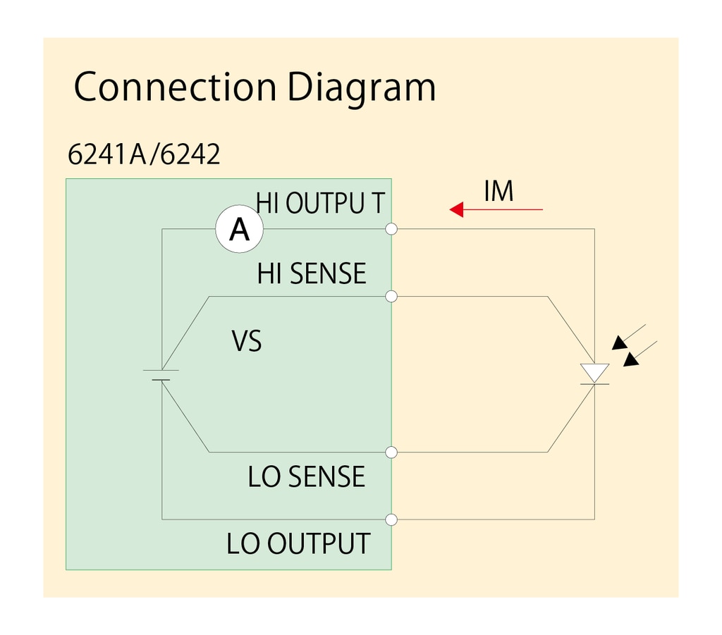
For evaluation of solar cells
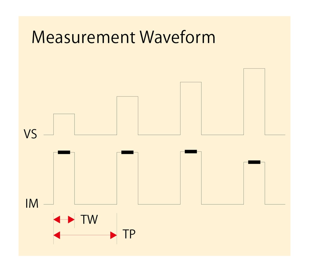
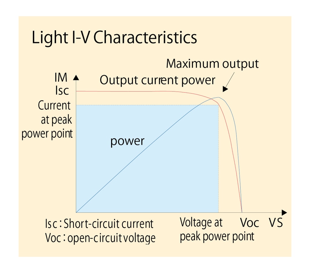
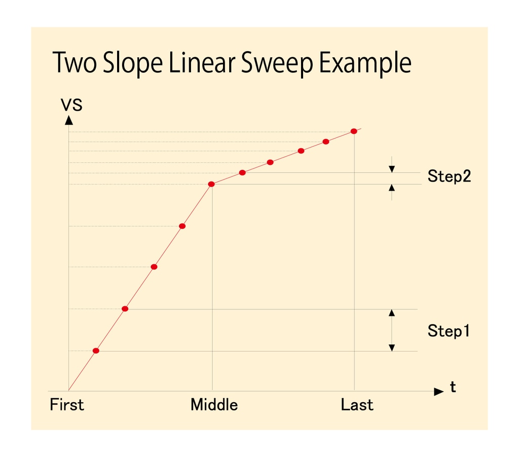
Since the conversion efficiency of a solar cell is influenced by bias application time, measurement by pulse application is effective in finding the true conversion efficiency. By using the pulse sweep function of the 6241A/6242, the I-V curve can be measured at high speed. Furthermore, by changing the pulse width, the change in characteristics depending on the application time can be measured easily. In addition, the two slope linear sweep function that can switch the step value during measurement enables measurement from the vicinity of voltage at the peak power point to open-circuit voltage in small steps.
- Pulse measurement with a minimum pulse width of 50 μs and a minimum period of 2 ms
- Minimum voltage step: 10 μV (300 mV range)
- Two slope linear sweep
Sweeps by Step1 between First and Middle
Sweeps by Step2 between Middle and Last
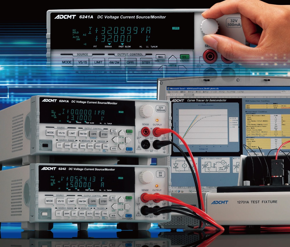
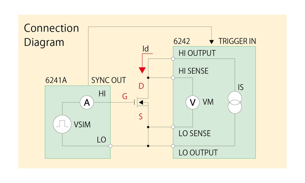
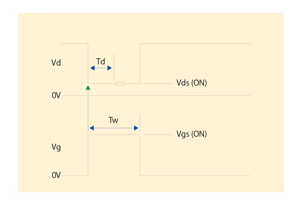
For ON-resistance measurement of MOSFET and analog switch
The following shows an example of ON-resistance measurement of MOSFET. The drain side is a 4-wire ISVM circuit. The current at ON state is determined by the source current (IS), and the drain voltage at OFF state is determined by the voltage limiter (VL). The gate side inputs the SYNC OUT signal to TRIGGER IN of the 6242 on the drain side as pulse source of VSIM. In this way, synchronous measurement by two units is achieved. The results of ON-resistance measurement can be displayed in ohms. In addition, by using the linear pulse sweep function on the gate side and the fixed sweep function on the drain side, gate voltage - ON resistance characteristics can be measured easily.
- Resistance measurement range: 6241A 2 μΩ to 1.6 GΩ
6242 0.2 μΩ to 304 MΩ - Maximum current (IdMax): 6241A 500 mA
6242 5 A - Pulse measurement with a minimum pulse width of 50 μs and a minimum period of 2 ms
- Gate current measurement with a resolution of 100 pA
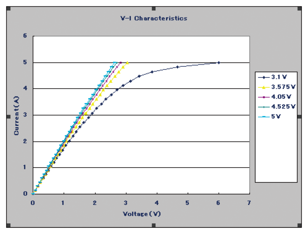
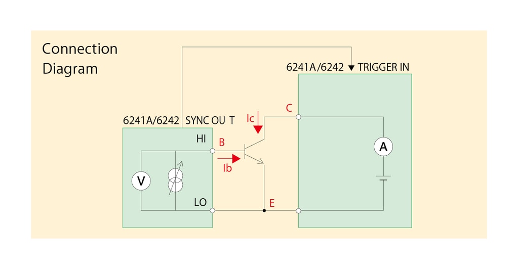
For DC characteristic evaluation of transistor and FET
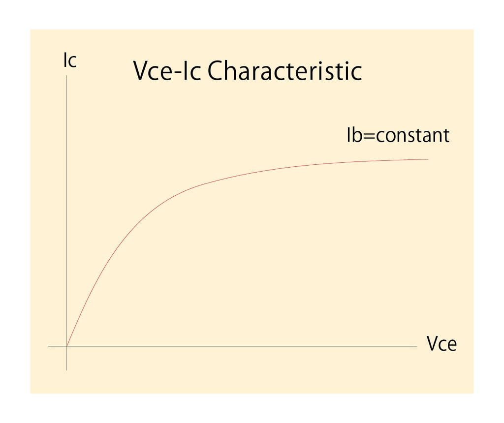
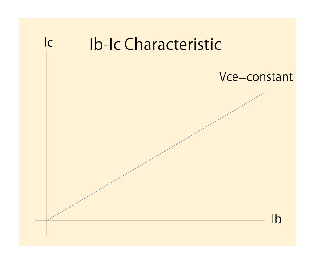
The following shows an example of transistor DC characteristic measurement using two units. In order to perform measurement by two units of the 6241A/6242 in synchronization, SYNC OUT of one unit on the base current (Ib) side is connected to TRIGGER IN of the other unit on the collector (Vce) side. In Vce-Ic characteristic measurement, the collector current (Ic) is measured by sweeping the collector-emitter voltage (Vce) of one unit with the base current (Ib) on the other unit remaining constant. In Ib-Ic characteristic measurement, by sweeping the base current (Ib) on one unit, the collector current (Ic) is measured by the other synchronized unit.
- DC/pulse sweep function
- Maximum setting range: ± 32 V/± 500 mA (6241A)
±6 V/±5 A (6242) - Measurement resolution: 1 μV/100 pA
- Pulse measurement with a minimum pulse width of 50 μs and a minimum period of 2 ms
- Synchronous operation
Specifications
| 6241A | 6242 | ||
| Number of digits for generation | 4½ | ||
| Output method | Bipolar | ||
|
Maximum output (top) Minimum resolution (bottom) |
Voltage |
±32 V/0.5 A |
±6 V/5 A |
| 10 μV | |||
|
Current |
±0.5 A/32 V | ±5 A/ 6V | |
| 1 nA | |||
| Number of digits for measurement | 5½ | ||
| Accuracy (typical range) | 0.02 % | ||
| Minimum measurement resolution | Voltage | 1 μV | |
| Current | 100 pA | ||
| Maximum measurement resistnace / Minimum resolution |
1.6 GΩ/2 μΩ | 304 MΩ/0.2 μΩ | |
| Pulse application / Measurement | Available | ||
| Minimum pulse width | 50 μs | ||
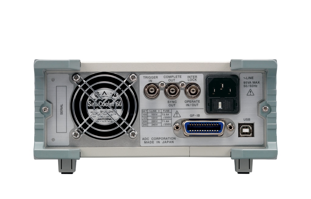
| Interface | USB, GPIB | ||
*For the detailed specifications, please download the brochure from "Download."
Appearance
Optional Accessories
| Name | Part Number |
| Input cable (banana (4 pins) - Kelvin) | A01006 |
| BNC-BNC cable (1.5 m) | |
| Input cable (test probe) | A01041 |
| Input and output cable (safety plug) | A01044 |
| Input and output cable (large current 0.5 m) | A01047-01 |
| Input and output cable (large current 1 m) | A01047-02 |
| Input and output cable (large current 1.5 m) | A01047-03 |
| Input and output cable (large current 2 m) | |
| Test fixture | 12701A |
| Banana tip adapter (for A01044) | A08531 |
| Alligator clip adapter (for A01044) | A08532 |
| Panel mount set (2U half) | A02039 |
| Panel mount set (2U half twin) | A02040 |
| Rack mount set (JIS 2U half) | A02263 |
| Rack mount set (JIS 2U half twin) | A02264 |
| Rack mount set (EIA 2U half) | A02463 |
| Rack mount set (EIA 2U half twin) | A02464 |
Download
Function: (1) Graphical display of measured data (2) Data acquisition (3) Remote command setting
*Go to the download page.

