
|  |
|  |
|  |
|  |
|  |
|
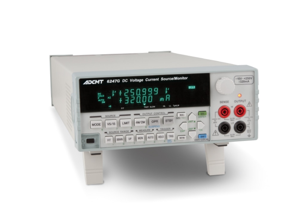
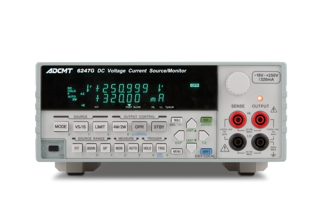
DC Voltage Current Source/Monitor
6247C / 6247G
- Wide ranging source and measurement
Voltage: -15 V to +250 V Current: 0 to ±320 mA - Source resolution of 100 μV/100 pA
- 5½-digit display (±320999) with measurement resolution of 10 μV/10 pA
- Basic source and measurement accuracy of ±0.02%
- Pulse measurement with minimum pulse width of 50 μs and resolution of 1 μs
- Sink-enabled bipolar output
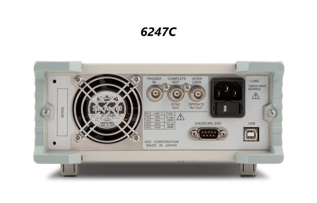
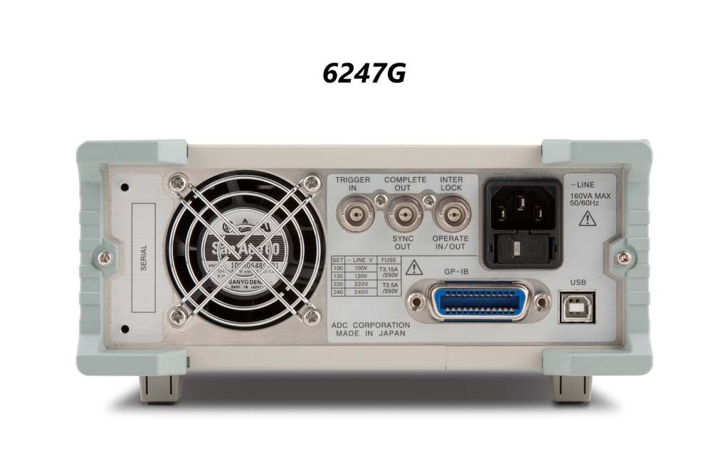
- GPIB (6247G), RS232 (6247C) and USB (6247G/6247C)
The 6247C/6247G is a DC voltage current source/monitor designed for evaluating high voltage semiconductors and LED luminaires that demand high efficiency and low power consumption, capable of outputting voltage up to +250 V and current up to ±320 mA. It provides high accuracy of ±0.02 % with 4½-digit source resolution and 5½-digit measurement resolution.
The 6247C/6247G features the well-established VSIM, ISVM, sweep and pulse generation functions. Also, leak current measurement up to 10 pA is possible. In addition, it is equipped with the various types of sweep functions such as linear, fixed, random and two slope linear sweep functions, the pulse measurement function with the minimum pulse width of 50 μs, the micro voltage and current measurement function with the minimum resolution of 10 μV or 10 pA, and the suspend function that controls the optimized output status. By using these functions, the 6247C/6247G can be widely used for evaluating or testing semiconductor and other electronic components in R&D fields and production lines.


Features
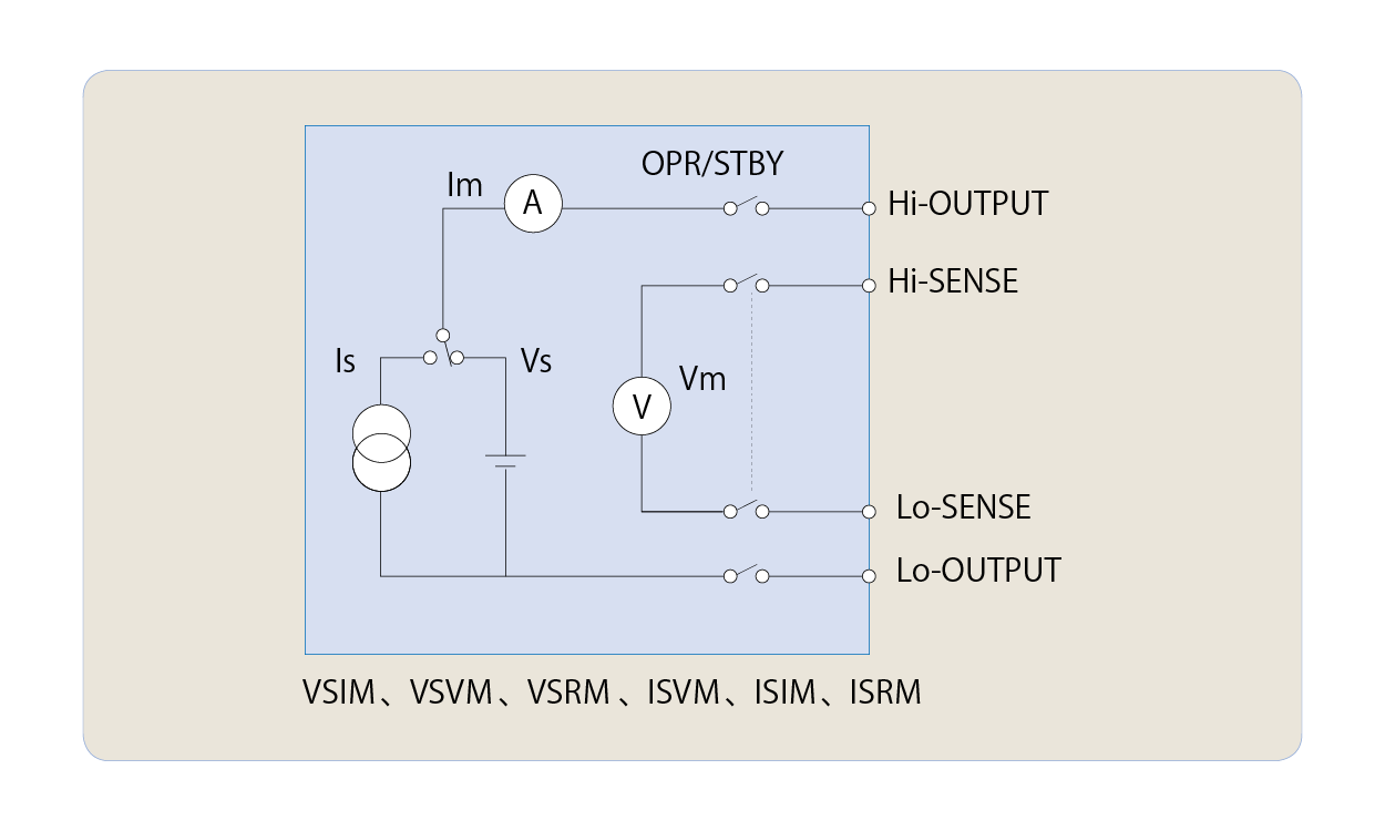
Voltage and current source mode
Voltage source, current source, voltage measurement, current measurement and resistance measurement are available by specifying the source and measurement functions.
Output range
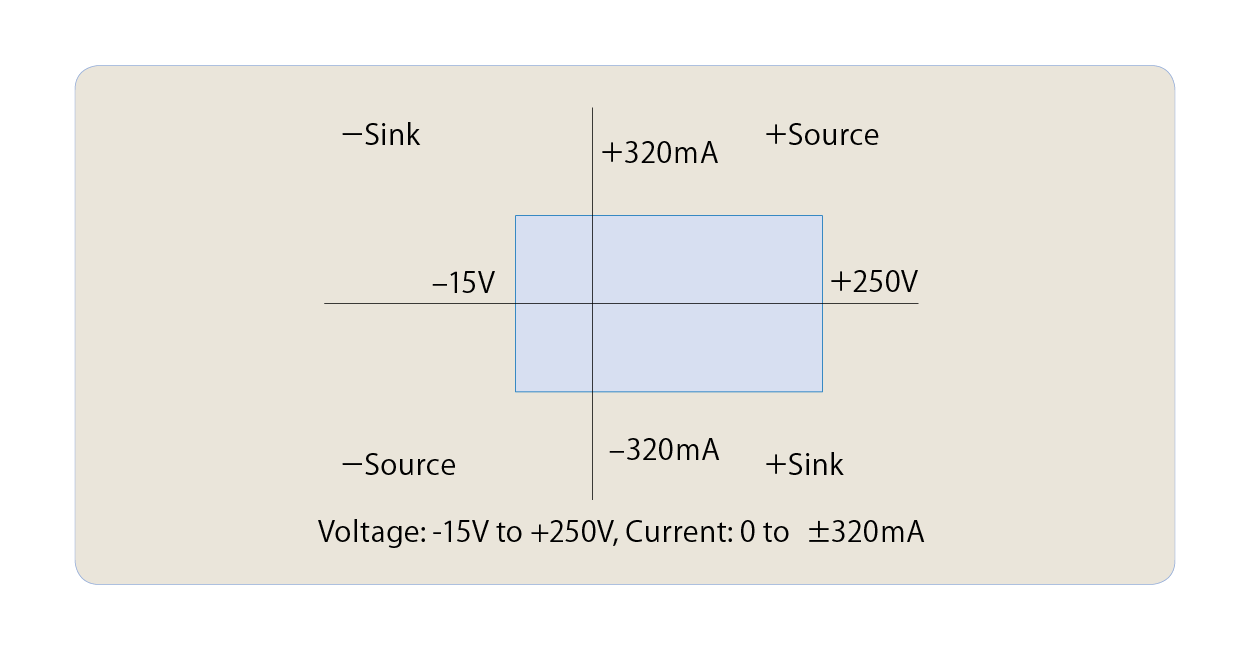
Voltage and current source mode
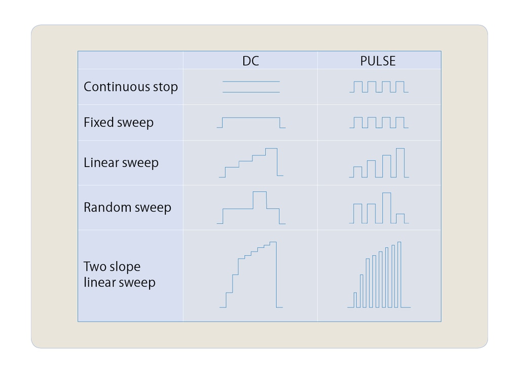
There are four source modes; DC, pulse, DC sweep, pulse sweep. Then, the sweep modes are classified into four sweep types: fixed sweep, linear sweep, random sweep (any type of waveform generation by user's programming), two slope linear sweep (linear sweep with step value switching). The minimum pulse width is 50 µs. The minimum cycle is 2 ms, or 500 µs without measurement.
HI/LO limiters separate setting
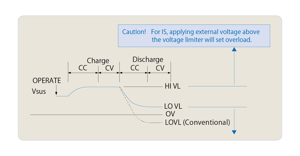
In voltage or current source, the HI/LO limiter settings are very important. The 6247C/6247G has a function that can set the HI and LO limiters individually. Furthermore, for the voltage-limiter, both HI and LO limiters can be set homo-polar. This prevents a capacitor or a battery from being over-discharged. Also, it is suitable for evaluating devices such as LDs that are used at a constant current and do not tolerate reverse voltage application.
Suspend function
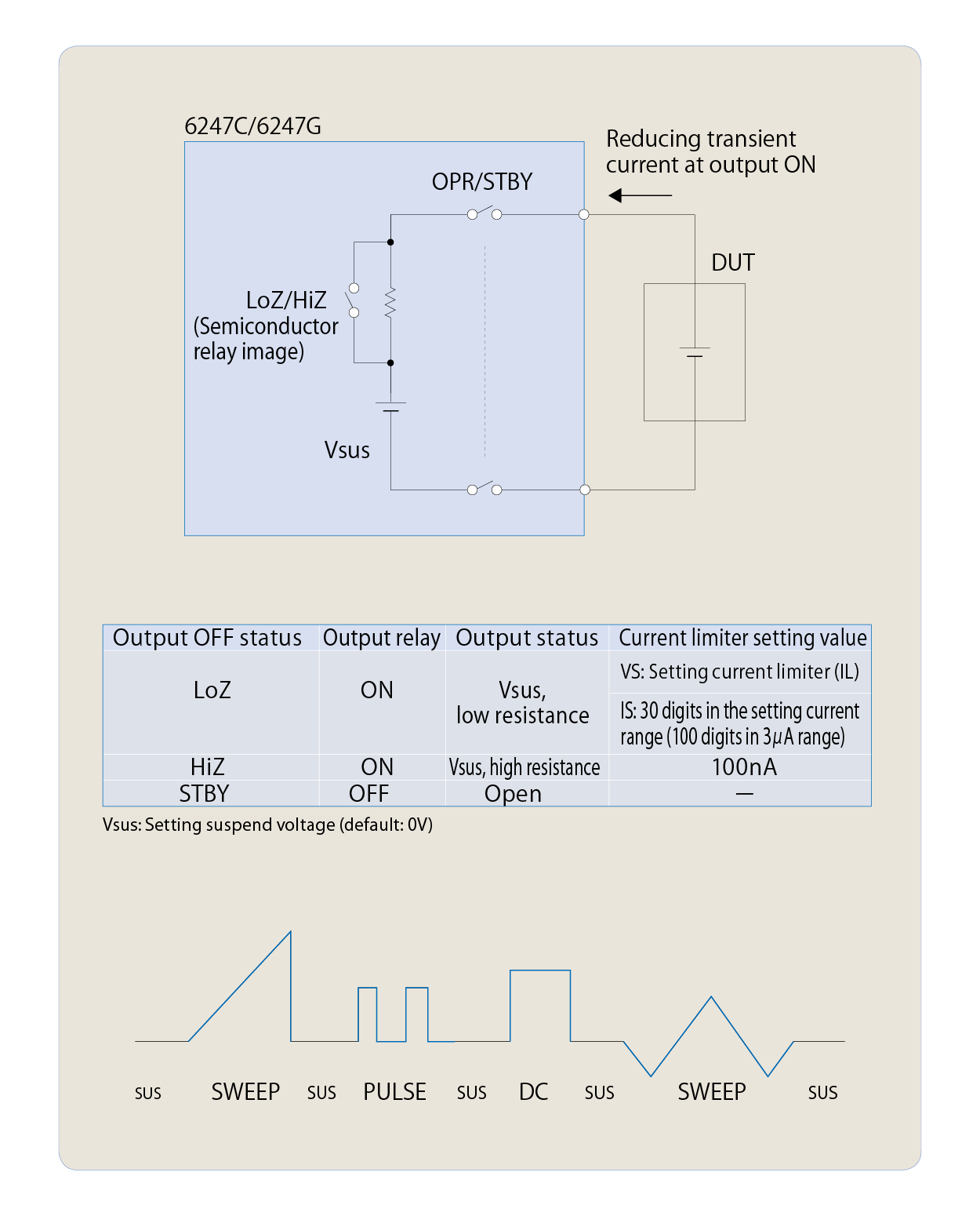
The 6247C/6247G can select from three output OFF statuses; STBY (output relay OFF), HiZ (output relay ON and high resistance), and LoZ (output relay ON and low resistance). Using this function can omit unnecessary relay ON/OFF operations, which extends the relay lifetime and improves the system throughout.
In addition, the setting of a suspend voltage (voltage in HiZ and LoZ status) can prevent transient current from being generated when connecting voltage sourcing devices such as batteries.
When a conventional generator or electronic load is connected with a battery, the output voltage is 0 V, and then the setting current starts flowing. In this case, the moment that it is connected, transient current sink occurs, causing unnecessary battery discharge. On the other hand, by setting the suspend voltage, the 6247C/6247G is connected in high-impedance state at the specified voltage and then the setting current flows. This prevents unnecessary discharge at the connection to the battery. For the 6247C/6247G, the source modes can be switched in such suspend status, which improves the throughput. (Continuous testing is possible without disconnecting DUTs.)
Current application response
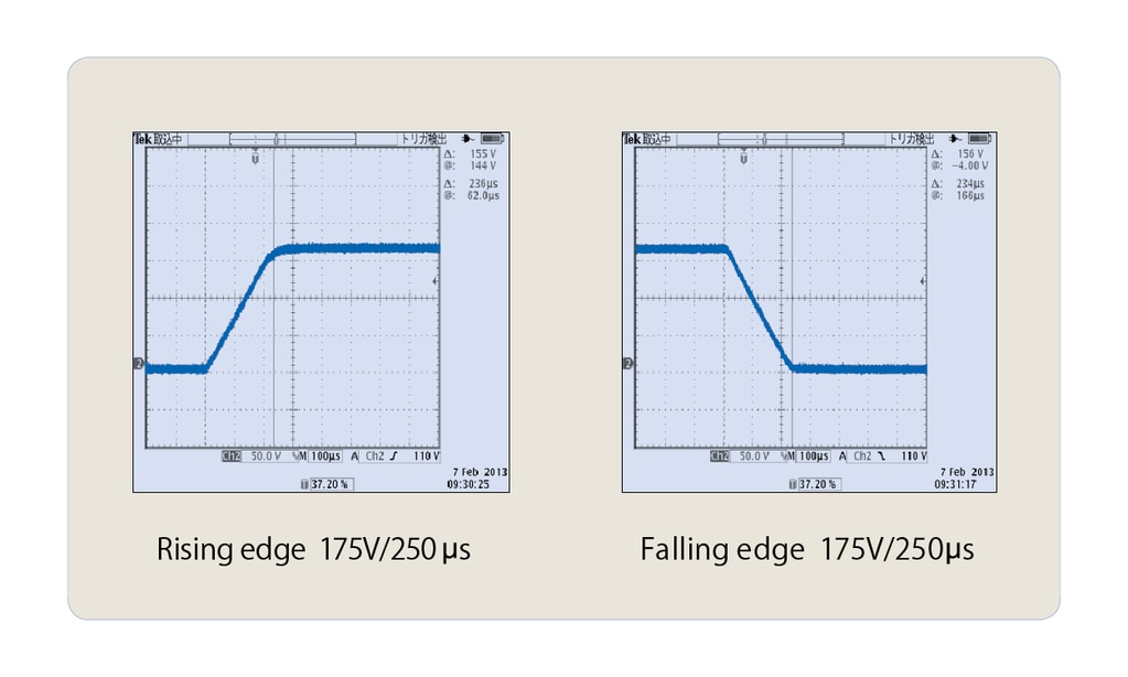
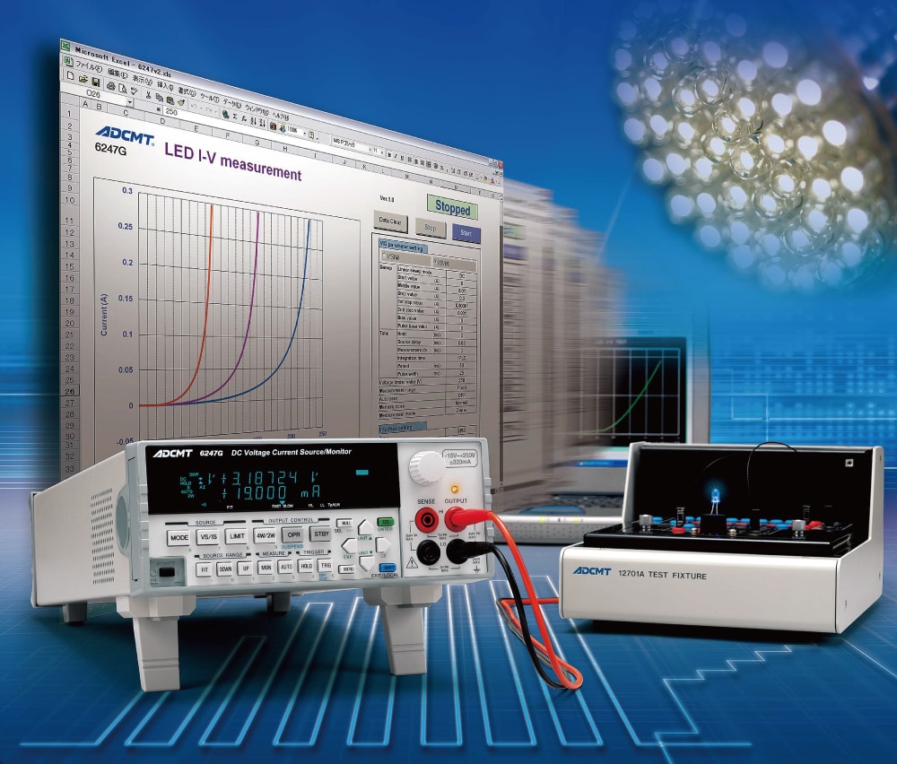
LED evaluation is done by ISVM (current source voltage measurement). When constant current is applied to a LED between 0 A and +IS, the output current becomes the setting current at the rising edge, but 0 A at the falling edge and the response time is very slow to discharge the device. To avoid this problem, current is applied between -IS and +IS. At this time, +VL is set to the forward voltage or higher and -VL to 0 V or minus several V to prevent reverse voltage application. The response when fifty white LEDs are connected in series is as follows:
+IS = +30 mA, -IS = -30 mA, +VL = +200 V, -VL = -5 V
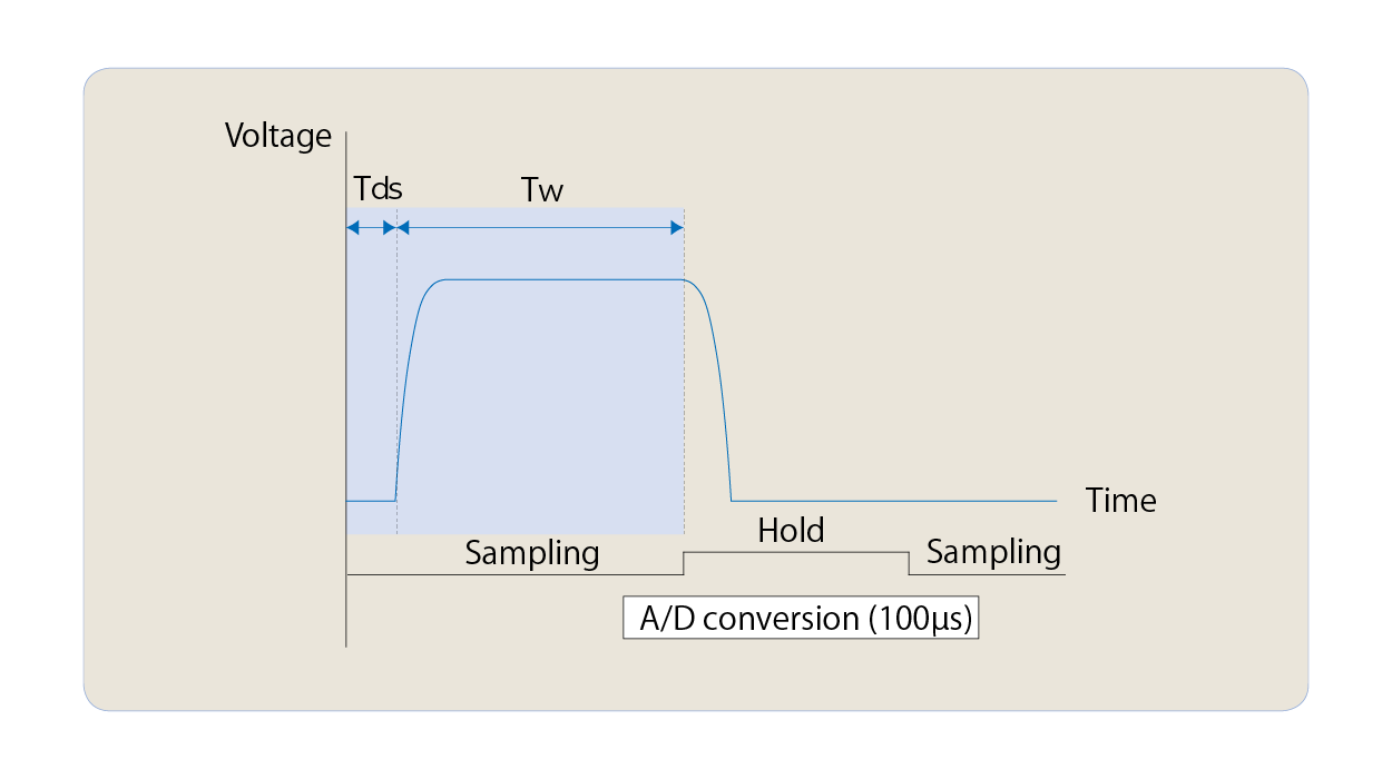
Sample Hold Measurement
Sample hold measurement is available in the pulse mode and the pulse sweep mode. Measurement holds an input signal immediately before pulse falling edge, and A/D conversion is implemented for integration time of 100 µs. This function enables precise values to be measured without setting the measurement delay time.
Applications
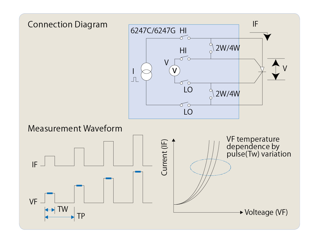
Diode temperature dependence evaluation
In I-V characteristic test on devices that generate heat when current flows, applying pulse current is effective for avoiding the influence of the self-heating. By using the current pulse sweep function and voltage measurement in synchronous with pulses, precise VF characteristic test with large current is available.
- Pulse sweep function
- Current setting range: 0 mA to ±320 mA
- Voltage measurement resolution: 10 µA
- Pulse measurement with minimum pulse width of 50 µs and minimum cycle of 2 ms
Diode leak current measurement
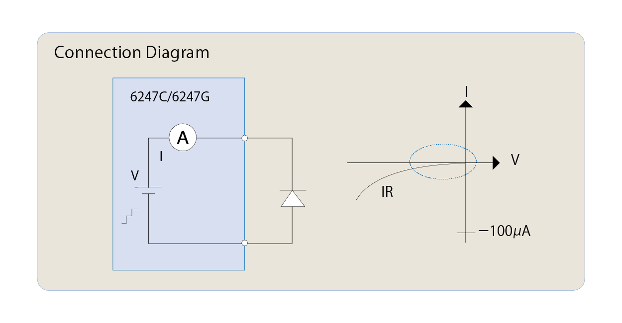
The 6247C/6247G is capable of ISVM (current source voltage measurement) and VSIM (voltage source current measurement). Diode I-V characteristics are measured by ISVM. In addition, micro leak current up to 10 pA can be measured by applying reverse voltage to diodes by VSIM. Also, automatic PASS/FAIL judgment is available by using comparison operation of the measurement calculating function.
- Sweep function
- Maximum setting range: -15 V to +250 V/±320 mA
- Current measurement resolution: 10 pA
- Measurement calculating function
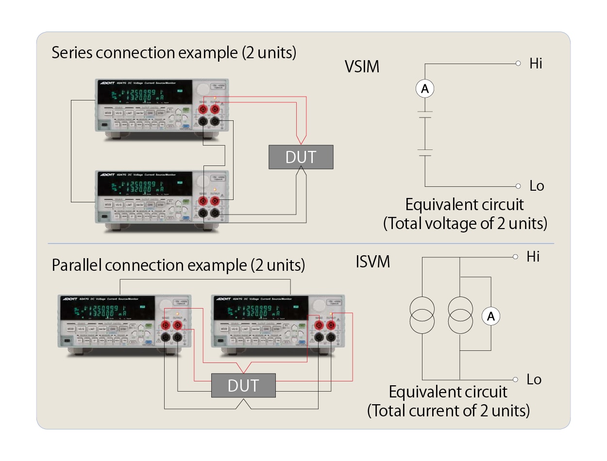
Higher voltage and larger current device testing
As the 6247C/6247G adopts floating bipolar output, the voltage capacity or current capacity can be increased by connecting more than two units in series or in parallel. Accordingly, it is capable of testing devices such as semiconductors that need higher voltage or larger capacity. For example, connecting two units in series outputs up to +500 V/±320 mA, or two units in parallel up to ±640 mA/+250 V. Similarly, the output level that you wish is available by connecting two units in series or more than two units in parallel.
| |
Number of units connected in series | ||
| 1 | 2 | ||
|
Number of units connected in parallel |
1 | + 250 V / 320 mA | + 500 V / 320 mA |
| 2 | + 250 V / 640 mA | + 500 V / 640 mA | |
| 3 | + 250V/ 960mA | + 500 V / 960 mA | |
|
" |
" | " | |
LED pulse width modulation brightness evaluation
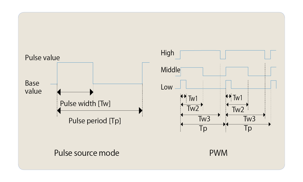
To control the LED brightness, generally the pulse width modulation (PWM) method is used. PWM requires the constant pulse current, the pulse width and the pulse period need to be varied. This can be easily done by using the pulse source mode of the 6247C/6247G.
- Pulse source mode
- Maximum setting range: -15 V to +250 V/±320 mA
- Pulse width: 50 µs to 59998 ms
- Pulse period: 500 µs to 60000 ms
Specifications
| 6247C | 6247G | ||
| Number of digits for generation | 4½ | ||
| Output method | Bipolar | ||
|
Maximum output (top) Minimum resolution (bottom) |
Voltage |
+250 V, -15 V/320 mA |
|
| 100 μV | |||
|
Current |
±320 mA/+250 V, -15 V | ||
| 100 pA | |||
|
Number of digits for measurement |
5½ | ||
| Accuracy (typical range) | 0.02 % | ||
| Minimum measurement resolution | Voltage | 10 μV | |
| Current | 10 pA | ||
| Maximum measurement resistnace / Minimum resolution |
125 GΩ/30 μΩ | ||
| Pulse application / Measurement | Available | ||
| Minimum pulse width | 50 μs | ||
| Interface | USB, RS232 | USB, GPIB | |
*For the detailed specifications, please download the brochure from "Download."
Appearance
Optional Accessories
| Name | Part Number |
| Test fixture | 12701A |
| Input cable (test probe) | A01041 |
| Input and output cable (safety plug) | A01044 |
| Input and output cable (large current 0.5 m) | A01047-01 |
| Input and output cable (large current 1 m) | A01047-02 |
| Input and output cable (large current 1.5 m) | A01047-03 |
| Input and output cable (large current 2 m) | |
| BNC-BNC cable (1.5 m) | A01036-1500 |
| Banana tip adapter (for A01044) | A08531 |
| Alligator clip adapter (for A01044) | A08532 |
| Panel mount set (2U half) | A02039 |
| Panel mount set (2U half twin) | A02040 |
| Rack mount set (JIS 2U half) | A02263 |
| Rack mount set (JIS 2U half twin) | A02264 |
| Rack mount set (EIA 2U half) | A02463 |
| Rack mount set (EIA 2U half twin) | A02464 |
Download
Sample programs described on the Operation Manual
*Go to the download page.

